Building a wireless sensor network simulation in SENSE consists of the following steps:
Here, we assume that all components needed by a sensor node component are available from the component repository. If this is not the case, the user must develop new components, as described by other tutorials. We should also mention that the first step of designing a sensor node component is not always necessary, if a standard sensor node is to be used.
This first line of this source file demands that HeapQueue must be used as the priority queue for event management. For wireless network simulation, because of the inherent drawback of CalendarQueue, and also because of the particular channel component being used, HeapQueue is often faster.
#define queue_t HeapQueue |
This header file is absolutely required
#include "../../common/sense.h" |
The following header files are necessary only if the corresponding components are needed by the sensor node component
#include "../../app/cbr.h" #include "../../mob/immobile.h" #include "../../net/flooding.h" #include "../../net/aodvi.h" #include "../../net/dsri.h" #include "../../mac/null_mac.h" #include "../../mac/mac_80211.h" #include "../../phy/transceiver.h" #include "../../phy/simple_channel.h" #include "../../energy/battery.h" #include "../../energy/power.h" #include "../../util/fifo_ack.h" |
#cxxdef is similar to #define, except it is only recognized by the
CompC++ compiler. The following two lines state that the flooding
component will be used for the network layer. These two macros
can also be overridden by command line macros definitions (whose
format is '-D
#cxxdef net_component Flooding #cxxdef net_struct Flooding_Struct |
For layer XXX, XXX_Struct is the accompanying class that defines data structures and types used in that layer. The reason we need a separate class for this purpose is that each XXX is a component, and that due to the particular way in which the CompC++ compiler was implemented data structures and types defined inside any component is not accessible from outside. Therefore, for each layer XXX, we must define all those data structures and types in XXX_Struct, and then derive component XXX from XXX_Struct.
The following three lines state:
typedef CBR_Struct::packet_t app_packet_t; typedef net_struct<app_packet_t>::packet_t net_packet_t; typedef MAC80211_Struct<net_packet_t*>::packet_t mac_packet_t; |
Now we can begin to define the sensor node component. First we instantiate every subcomponent used by the node component. We need to determine the template parameter type for each subcomponent, usually starting from the application layer. Normally the application layer component does not have any template parameter.
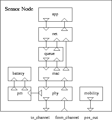
This picture shows the internal structure of a sensor node.

component SensorNode : public TypeII
{
public:

    CBR app;
    net_component <app_packet_t> net;
    MAC80211 <net_packet_t*> mac;
    // A transceiver that can transmit and receive at the same time (of course
    // a collision would occur in such cases)
    DuplexTransceiver < mac_packet_t > phy;
    // Linear battery
    SimpleBattery battery;
    // PowerManagers manage the battery
    PowerManager pm;
    // sensor nodes are immobile
    Immobile mob;
    // the queue used between network and mac
    FIFOACK3<net_packet_t*,ether_addr_t,unsigned int> queue;

    double MaxX, MaxY;  // coordinate boundaries
    ether_addr_t MyEtherAddr; // the ethernet address of this node
    int ID; // the identifier

    virtual ~SensorNode();
    void Start();
    void Stop();
    void Setup();
|
The following lines define one inport and two outports to be connected to the channel components.
	outport void to_channel_packet(mac_packet_t* packet, double power, int id);
	inport void from_channel (mac_packet_t* packet, double power);
	outport void to_channel_pos(coordinate_t& pos, int id);
};

SensorNode::~SensorNode()
{
}

void SensorNode::Start()
{
}

void SensorNode::Stop()
{
}
|
This function must be called before running the simulation.
void SensorNode::Setup()
{
|
At the beginning the amount of energy in each battery is 1,000,000 Joules.
battery.InitialEnergy=1e6;
|
Each subcomponent must als know the ethernet address of the sensor node it resides. Remember the application layer is a CBR component, which would stop at FinishTime to give the whole network an opportunity to clean up any packets in transit. Assiging false to app.DumpPackets means that if COST_DEBUG is defined, app still won't print out anything.
    app.MyEtherAddr=MyEtherAddr;
    app.FinishTime=StopTime()*0.9;
    app.DumpPackets=false;
|
Set the coordinate of the sensor node. Must also give ID to mob since ID was used to identify the index of the sensor node when the position info is sent to the channel component.
    mob.InitX=Random(MaxX);
    mob.InitY=Random(MaxY);
    mob.ID=ID;
|
When a net component is about to retransmit a packet that it received, it cannot do so because otherwise all nodes that received the packet may attempt to retransmit the packet immediately, inevitably resulting in a collision. ForwardDelay gives the maximum delay time a needed-to-be-retransmit packet may incur. The actual delay is randomly chosen between [0,ForwardDelay].
    net.MyEtherAddr=MyEtherAddr;
    net.ForwardDelay=0.1;
    net.DumpPackets=true;
|
If Promiscuity is ture, then the mac component will forward every packet even if it not destined to this sensor node, to the network layer. And we want to debug the mac layer, so we set mac.DumpPackets to true.
    mac.MyEtherAddr=MyEtherAddr;
    mac.Promiscuity=true;
    mac.DumpPackets=true;
|
The PowerManager takes care of power consumption at different states. The following lines state the power consumption is 1.6W at transmission state, 1.2 at receive state, and 1.115 at idle state.
pm.TXPower=1.6; pm.RXPower=1.2; pm.IdlePower=1.15; |
phy.TxPower is the transmission power of the antenna. phy.RXThresh is the lower bound on the receive power of any packet that can be successfuly received. phy.CSThresh is the lower bound on tye receive power of any packet that can be detected. phy also needs to know the id because it needs to communicate with the channel component.
    phy.TXPower=0.0280;
    phy.TXGain=1.0;
    phy.RXGain=1.0;
    phy.Frequency=9.14e8;
    phy.RXThresh=3.652e-10;
    phy.CSThresh=1.559e-11;
    phy.ID=ID;
|
Now we can establish the connections between components. The connections will become much clearer if we look at the diagram.
    connect app.to_transport, net.from_transport;
    connect net.to_transport, app.from_transport;

    connect net.to_mac, queue.in;
    connect queue.out, mac.from_network;
    connect mac.to_network_ack, queue.next;
    connect queue.ack, net.from_mac_ack;
    connect mac.to_network_data, net.from_mac_data ;
|
These three lines are commented out. They are used when the net component is directly connected to the mac component without going through the queue.
    //connect mac.to_network_data, net.from_mac_data ;
    //connect mac.to_network_ack, net.from_mac_ack;
    //connect net.to_mac, mac.from_network;

    connect mac.to_phy, phy.from_mac;
    connect phy.to_mac, mac.from_phy;

    connect phy.to_power_switch, pm.switch_state;
    connect pm.to_battery_query, battery.query_in;
    connect pm.to_battery_power, battery.power_in;
|
These three connect statements are different. All above ones are between an outport of a subcomponent and an outport of another subcomponent, while these three are between a port of the sensor node and a port of a subcomponent. We can view these connections as mapping from the ports of subcomponents to its own ports, i.e., to expose the ports of internal components. Also remember the connect statement is so designed that it can take only two ports, and than packets always flow through from the first port to the second port, so when connection two inports, the inport of the subcomponent must be placed in the second place.
    connect phy.to_channel, to_channel_packet;
    connect mob.pos_out, to_channel_pos;
    connect from_channel, phy.from_channel;
}
|
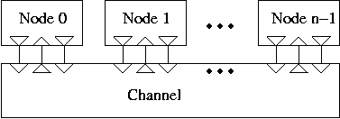
Once we have the sensor node component ready, we can start to build the entire simulation, which is named RoutingSim. It must be derived from the simulation engine class CostSimEng. This is the structure of the network.

component RoutingSim : public CostSimEng
{
public:
    void Start();
    void Stop();
|
These are simulation parameters. We don't want configurators of the simulation to access the parameters of those inter-components.
    double MaxX, MaxY;
    int NumNodes;
    int NumSourceNodes;
    int NumConnections;
    int PacketSize;
    double Interval;
|
Here we declare sense nodes as an array of SensorNode, and a channel component.
    SensorNode[]  nodes;
    SimpleChannel < mac_packet_t > channel;

    void Setup();
};

void RoutingSim :: Start()
{

}
|
After the simulation is stopped, we will collect some statistics.
void RoutingSim :: Stop()
{
    int i,sent,recv;
    double delay;
    for(sent=recv=i=0,delay=0.0;i<NumNodes;i++)
    {
		sent+=nodes[i].app.SentPackets;
		recv+=nodes[i].app.RecvPackets;
		delay+=nodes[i].app.TotalDelay;
    }
    printf("APP -- packets sent: %d, received: %d, success rate: %.3f, delay: %.3f\n",
		sent,recv,(double)recv/sent,delay/recv);
    for(sent=recv=i=0;i<NumNodes;i++)
    {
		sent+=nodes[i].net.SentPackets;
		recv+=nodes[i].net.RecvPackets;
    }
    printf("NET -- packets sent: %d, received: %d\n",sent,recv);
    for(sent=recv=i=0;i<NumNodes;i++)
    {
		sent+=nodes[i].mac.SentPackets;
		recv+=nodes[i].mac.RecvPackets;
    }
    printf("MAC -- packets sent: %d, received: %d\n",sent,recv);
}
|
The simulation has a Setup() function which must be called before the simulation can be run. The reason we don't do this in the constructor is that we must assign values to its parameters after the simulation component has been instantiated. The Setup() function, which you can rename to anything you like, first maps component parameters to corresponding simulation parameters (for instance, assign the value of the simulation parameter interval to the component parameter source.interval). It then connects pairs of inport and outports.
void RoutingSim :: Setup()
{
    int i,j;
|
The size of the sensor node array must be set using SetSize() before the array can ever be used.
    nodes.SetSize(NumNodes);
    for(i=0;i<NumNodes;i++)
    {
		nodes[i].MaxX=MaxX;
		nodes[i].MaxY=MaxY;
		nodes[i].MyEtherAddr=i;
		nodes[i].ID=i;
	    nodes[i].Setup(); // don't forget to call this function for each sensor node
    }
|
The channel component needs to know the total number of sensor nodes. It also needs to know the value of CSThresh since it won't sent packets to nodes that cann't detect them. RXThresh is also needed to produce the same receive power in those nodes that can just correctly recieve packets when using different propagation models.
In this example FreeSpace is used.
    channel.NumNodes=NumNodes;
    channel.DumpPackets=false;
    channel.CSThresh=nodes[0].phy.CSThresh;
    channel.RXThresh=nodes[0].phy.RXThresh;
    channel.PropagationModel=channel.FreeSpace;
|
The channel component also has a Setup() function which is to set the size of its outport array.
    channel.Setup();

    for(i=0;i<NumNodes;i++)
    {
		connect nodes[i].to_channel_packet,channel.from_phy;
		connect nodes[i].to_channel_pos,channel.pos_in;
		connect channel.to_phy[i],nodes[i].from_channel ;
    }
|
This is to create communication pairs.
    int src,dst;
    for(i=0;i<NumSourceNodes;i++)
    {
		for(j=0;j<NumConnections;j++)
		{
	    	do
	    	{
				src=Random(NumNodes);
				dst=Random(NumNodes);
	    	}while(src==dst);
	    	nodes[src].app.Connections.push_back(
				make_triple(ether_addr_t(dst),Random(PacketSize)+PacketSize/2,
				Random(Interval)+Interval/2));
		}
    }
}
|
To compile the program, enter:
../../bin/cxx sim_routing.cc
g++ -Wall -o sim_routing sim_routing.cxx
To run the simulation, simply type in:
sim_routing [StopTime] [NumNodes] [MaxX] [NumSourceNodes] [PacketSize] [Interval]
int main(int argc, char* argv[])
{
    RoutingSim sim;

    sim.StopTime = 1000;
    sim.Seed = 1234;

    sim.MaxX = 2000;
    sim.MaxY = 2000;

    sim.NumNodes = 110;
    sim.NumConnections = 2;
    sim.PacketSize = 2000;
    sim.Interval = 100.0;

    if(argc >= 2) sim.StopTime = atof(argv[1]);
    if(argc >= 3) sim.NumNodes = atoi(argv[2]);
    sim.NumSourceNodes = sim.NumNodes / 10;
    if(argc >= 4) sim.MaxX = sim.MaxY = atof(argv[3]);
    if(argc >= 5) sim.NumSourceNodes = atoi(argv[4]);
    if(argc >= 6) sim.PacketSize = atoi(argv[5]);
    if(argc >= 7) sim.Interval = atof(argv[6]);

    printf("StopTime: %.0f, Number of Nodes: %d, Terrain: %.0f by %.0f\n",
	   sim.StopTime, sim.NumNodes, sim.MaxX, sim.MaxY);
    printf("Number of Sources: %d, Packet Size: %d, Interval: %f\n",
	   sim.NumSourceNodes, sim.PacketSize, sim.Interval);

    sim.Setup();
    sim.Run();

    return 0;
}
|